Welcome to John's Blog World...

Welcome to my little sharing space--where I come to showcase some of my custom projects and to share "how-to" info with others out there. As a lifelong "maker", design enthusiast, and design professor, this blog explains some of the little projects I occasionally throw myself into, with the intent that I may help inspire others toward self-actualization and to show them how easy it really is to construct and realize their own ideas and dreams. As Brancusi said, "Create like a god, work like a slave."

Tuesday, February 22, 2011

DIY iPod Touch Docking Station -- Prototyping With Acrylic Plastic

So, let’s say you’ve got an idea for a sweet design—a design that needs to be lightweight, weather resistant, inexpensive, and easily fabricated. Maybe it even needs to be clear, which would suddenly make this design a tall order to fill. Well, if you look at traditional materials to fit the bill, then you'll find that wood is lightweight and easy to work with in the shop, but it’s not all that weather resistant, and it sure ain’t clear. Metal is a durable, useful option, but it can require some expensive tools to fabricate parts with, especially if welded joints are required. On top of that, metal isn't transparent (unless you have some great top-secret leads on alien technology), and it can be heavy and have limited weather resistance, depending on the particular metal you select. But, If you want a prototyping material that fits all of these requirements at the same time, you might look into the "magical" world of wonderful substances we commonly refer to as “plastics”. 
In modern life, we use plastics more frequently and extensively than most people even recognize, but they are often already formed into products and can be difficult to reuse or reappropriate for our own specific use—unless you know about thermoplastic sheet materials...like acrylic. Acrylic plastic (or polymethylmethylacrylate--PMMA--for those of you who want to use the long name to lay down the nerd card at your next Jeopardy party) is one of the most easily obtained and usable thermoplastics and is also sold under the trade names of Plexiglas and Lucite. Like many traditional building materials, acrylic has the benefit of being solid at room temperature and easily worked using common shop tools. But, unlike typical materials, acrylic can be quickly and easily formed with inexpensive heating tools--which opens up a world of shaping possibilities that other materials simply don't possess.  
Acrylic plastics can be purchased in a couple of different forms, but for quick prototyping purposes using power and hand tools, it tends to be easiest to use in its common sheet form. Compared with traditional materials, it can be somewhat expensive in thick sections, or when large sheets are required, but is relatively cheap when procured in pre-cut sizes or as scrap. This can be helpful for the do-it-yourselfer who may be working on a small prototype or project, since these smaller scrap sizes are generally easier to transport, manage, and work with anyway. Acrylic sheet plastic is also available in many colors (either opaque or transparent), and can be easily painted using common automotive paints. One caution on using acrylic plastic, however, is that it doesn't have the same impact resistance as the plastics typically found in mass-manufactured consumer goods, like ABS, polycarbonate, or polypropylene. Therefore, take care to avoid dropping, overstressing, or overloading acrylic plastics since they can chip or fracture without much effort.
To demonstrate the ease of working with acrylic sheet, this blog posting will walk through the steps needed to fabricate a custom iPod Touch docking station (shown below). Although this docking station has a rather simple design, the methods shown here illustrate some of the common cutting, finishing, and forming steps that could be used to produce just about any prototype that would benefit from acrylic's useful material properties.
As a bit of background, I first started working with acrylic sheet when I was in a shop class in middle school--and I have to admit that I became totally enamored by the stuff. As I recall, the first project I made was a cheesy little 80's unicorn clock for one of my sisters. But I couldn't just stop there--the fabrication possibilities provided by acrylic were beckoning me to do even more. At the time, I was way into writing and illustrating comic books and started buying large pieces of acrylic plastic from my shop teacher so that I could make full-body suits of armor like the characters in my stories had. Luckily, I never had to go into battle with any of that plastic armor, but it sure helped me develop my skills in working with plastics at a young age.
When working with acrylic sheet, it's important to develop your design from the beginning so that it can be fabricated from flat stock. If you've got a design with all kinds of crazy compound curves and wacky form to it, you're going to be in for some serious headaches (although such shapes may still be possible with a lot of work--and assuming that you like the mental pain). However, if you intend for your design to rely on simple bends, flat pieces, or even modest glue joints, you should be able to make it without much trouble. Also, keep in mind that thicker plastics don't bend very well (or easily), so if your design has lots of tight bends in it, thinner plastic is advisable. Generally speaking, I shy away from plastic over 1/4" thick when I'm doing a lot of bending. Plastic that is around 1/8" thick works very well for most small projects like this.
To get started with this little demo project, I first created some quick sketches to explore a few shape and function possibilities for the docking station. I settled on a basic chair-like form that would proudly display the iPod while allowing for straightforward mounting of the stock Apple dock connector/USB cable to the finished acrylic base. Using these sketches, I cut and folded some paper to make a quick mock-up of the docking station so that I could be assured that the size and proportion was correct (see below).  
Once I was content with my design direction, I unfolded the paper mock-up to make the cutting pattern for the plastic. I also used a pen and ruler to mark the location of the bends so I could reference these later in the building process.
Next I traced the pattern onto the acrylic sheet. Acrylic typically comes with a backing of either paper or plastic film on it to minimize scratches. It's usually best to keep the backing on for as long as possible during the fabrication process to avoid the hassle of unnecessary buffing and polishing to scratched surfaces. I like to transfer the bend lines onto the acrylic backing film as well, because it comes in handy later on to remind me where I need to make all those bends.
Acrylic cuts very easily with a table saw, but I recommend special plastics cutting blades to keep the plastic from blowing out (or chipping) as the blade cuts through the sheet. These types of blades are pricey, so a fine-toothed carbide blade can work well instead. Remember to always use a push-stick (shown below) when cutting narrow pieces!...it helps keep those digits where they belong. Heck, that's why I've still got mine today.
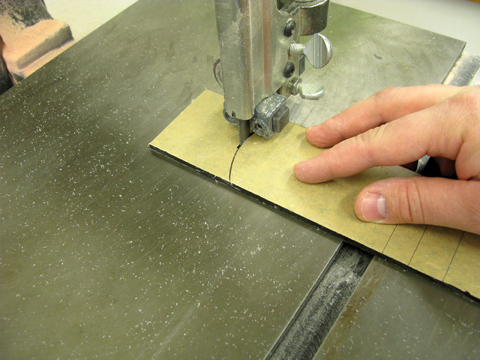
For curved cuts, the bandsaw works well. If I need to make really tight-radius shapes, relief cuts in the plastic can help keep the blade from binding around the curves. If the shape I'm cutting is just too insane for the bandsaw, I move my project over to the scroll saw since it's actually made to handle intricate and curvy shapes.
A belt or disc sander can help shape up the edges very quickly. But avoid using fine-grit or old, grit-less sandpaper since these will generate a lot of heat and end up melting the plastic more than sanding it.
Sanding with power tools will leave some heavy grit scratches in the edges of the plastic (as seen below). Such scratches really detract from the overall appearance of the project, so I spend the extra time to demonstrate a respectable level of craftsmanship by smoothing these imperfections out.
To create pretty, smooth edges, I go with the standard lineup of sandpaper, utility knife blade, and polishing compounds (shown below). The sandpaper knocks down waves and nasty, chunky grooves on the surface of the edges. A fresh razor blade in a utility knife can quickly scrape the surface clean while avoiding lots of time with progressive grits of sandpaper. And lastly, the polishing compound takes the fine scratches out of the surface and leaves a respectable, sparkly surface that shows how much you really cared to make your project look spiffy. Our shop is outfitted with polish that is made specifically for plastics, but course to fine automotive polishes will work well also.
When sanding straight surfaces, I always use a sanding block to reinforce the sandpaper. This helps produce a uniform sanding surface that levels any peaks and valleys in the plastic very quickly. I'm using a 220-grit sandpaper in this picture because it's generally sufficient to get the 100-grit grooves out of the plastic that were left by the power sander.
After leveling the edges, I usually take a utility knife (with a brand-new blade in it) or straight razor blade over the edge to scrape along and take out the 220-grit scratches. This method is just as effective as using 320-grit and then 400-grit sandpapers on the edges, but it's a whole lot less time intensive; it usually only takes a few passes and a few seconds rather than the several minutes required to actually sand the edges.
To get the edge ready for final smoothing, I use a fine-grit sandpaper to get rid of any small grooves that may have been left over by the knife blade. For this final fine-grit smoothing, wet sanding works best, though with paper-backed acrylic sheet, the paper starts to dissolve a bit and becomes messy and difficult to remove when finished. Consequently, if you've got paper-backed acrylic, just dry sand the edges with 500-grit sandpaper
Finally, I'm ready to do the polishing. I start with the "heavy scratch remover" first, which has a grit to it that is similar to traditional toothpastes...though I don't think I'd try brushing with it. (It just doesn't smell like something that I'd like to put in my mouth in the first place.)
I apply some good rubbing pressure with the polish to work the scratches out...
...and then move up to the "fine scratch remover" to bring the shine up even more. The final super-slick and sparkly polishing step really produces a mirror finish in the plastic.
As you can see in this finished edge, the polishing steps really pump up the bling.
Next, the plastic needs to be bent using some simple heating methods. To mark the location of the bends, I use a white colored pencil or grease pencil to transfer the bend lines from the paper backing to the edge of the plastic. This is an important step because it's difficult to find where the bends need to be once the backing paper has been removed...and it has to be removed before heating and bending.
Once I've got everything ready to start the bending processes, I peel off the backing paper and try to avoid scratching the surfaces while I'm handling the plastic.
For simple, straight bends, a strip heater (shown below) is a super-duper-awesome tool. A heat gun will also work well, but it tends to produce a wider, less controlled zone of heat on the plastic. If I need to heat the whole piece of plastic at once, I simply put it into the shop's oven at about 375 degrees Fahrenheit for a few minutes until the plastic gets soft and pliable. Always make sure to use gloves when touching any heated sections of the plastic--it can get very toasty!
Once the strip heater is plugged in, turned on, and allowed to pre-heat, I place the acrylic piece over the gap in the top surface of the strip heater, making sure to line up the bend marks on the edge with the heating element (shown below).
I try to flip the acrylic over periodically to help promote even heating on both sides of the piece. This makes bending the plastic much easier. As you can see in the picture below, acrylic sheet has such a perfectly smooth surface that it produces mirror-like reflections from overhead lights...at least until it starts to heat up to its bending point. When it gets sufficiently warm, the plastic begins to soften and deform a bit, causing ripples and warps in the surface reflections. I use these warped reflections as a way of gauging when the plastic is getting ready for bending.
When the heated plastic loosens up (and before it starts to sag) then it is ready to bend. Never try to bend acrylic that has not heated all the way through its thickness; it can catastrophically fracture if it is too cool when forced into a bend. To control a straight bend on a straight-sided shape, a table top works well to keep things in line. It's best to hold the plastic in place until the bent area has cooled to the point that it is only warm to the touch.
After a couple more rounds on the heat strip, the base for the docking station is fully formed. All that's left is to use a rotary tool (like a Dremel) with a cut-off wheel to cut a hole in the bottom through which the standard dock connection/USB cable can be epoxied in place and the iPod can be securely docked.
And there you have it--plastic simplicity, with lots of possibilities mixed in. Since the students in my plastics class are currently working on their own acrylic projects, I'll show off some of their work in an upcoming blog entry once I've picked the most impressive of the bunch.
Word.

Friday, January 21, 2011

DIY Kid's Camera -- FDM Prototype "Skinning" of Recycled Technology

I think, to a certain degree, I'm a technology hoarder. I have boxes and drawers of old electronics throughout the house (and garage) that I sometimes have difficulty parting with--either for sentimental reasons (like the first mini-disc player that I decided to modify) or for practical reasons (like my micro-cassette transcriber that I may use again someday...or not). Regardless, I've got a lot of extraneous, still usable but out-dated electronics kickin' around that I'm sure my wife would love to send to a landfill (but, thankfully, hasn't). With all that "stuff" tucked away, I thought it would be nice if I could use some of it again rather than getting even more "stuff"...and maybe even give some of that "stuff" a second life, so to speak, by finding a way to maintain its usefulness. With the pervasive American attitude that everything is replaceable, we seem to be fighting against ourselves in an ironic way--working longer and harder for more new stuff, while tossing out the perfectly good stuff we already. Much of our existing stuff may work just fine to fulfill many of our needs and wants (which is why we acquired them in the first place, right) if we only had the wherewithall to either refurbish, reuse, or reappropriate it. 
Some time ago, my wife and I started noticing how enthralled our daughter was whenever we gave her the opportunity to use our digital camera. We talked about getting one of those tough, cutesy, "kid" cameras out there, but after looking at several of the commercially available kids' cameras out there, and hearing mixed reviews, I noticed that they all had about the same functionality and each had its own set of quirks. One day it occurred to me that I could probably have some fun making an even more functional kid camera based on a small digital camera that I'd purchased while on business in Japan several years ago. It was a camera that I'd actually purchased as a birthday gift for myself as I celebrated that happy day all by myself in a 2 square foot hotel room in downtown Nagoya on a drab and wet autumn day--hence the sentimental reason that I kept it around even though I'd moved on to another more capable camera long ago. This particular camera was a tiny "credit card" camera made by Casio called the Exilim EX-S1. It had a body that is much smaller than many of the kid-specific cameras out there (about the size of a deck of cards), but I figured that its small form factor would give me some design flexibility in fashioning a new camera casing around it that was more appropriately sized for a kid. Coincidentally, most of the cameras out there made just for kids are unnaturally large for children's hands and could probably do with a little down-sizing in the design, anyway. I'm not sure why so many designers seem to think that kids would prefer big, dopey-looking stuff, but there is are designers out there (probably the ones without kids) that unquestioningly follow such misguided notions. As a parent, I've noticed that kids will often gravitate to those things they see adults using all the time...even though they may still have some inborn preferences for playful shapes and show interest in those as well. Obviously, any device for a child should be able to withstand the rigors of childhood play, but that doesn't mean that it needs to look goofy. So, I figured my little design exercise to reappropriating my old camera into something that my four-year would find even more useful--both functionally and aesthetically--meant that the new design would need to be tougher, but also "cuter".
This blog entry will show how I attempted to do that using solid modeling software and rapid prototyping...and also serves as an example to my students of what can be done using engineering and design constraints out of you control. It's one thing to build something when you've got maximum control over the placement and components within a device. It's a whole other ballgame when somebody has already called the shots about the architecture of the device and you've got to work around that. Bear in mind that this was not the cheap route to take. The scale of manufacture these days is such that it's usually cheaper to buy a new electronic somethin'-or-other than to fix it up. But I ain't always about cheaper--especially if there's something intrinsically interesting about the "fix it" project that I'd be attempting.
Below is a shot of what the final, unpainted camera looks like. The ABS plastic used by our FDM (Fused Deposition Modeling) machine comes in a few different colors (white, black, blue, red, etc.), but parts created on the machine also have a rough surface that requires additional finishing steps for best aesthetics. Of course, I'll show a painting and finishing demo for FDM parts in a later blog entry.
To get started with the new camera design, I had to get creative around all the existing physical constraints of the camera I was using. This meant that I had to take into consideration both its overall shape and functional components, like the lens, screen, and buttons. After making a proportionate sketch of the camera, I used this as a template from which I could make some quick sketches of new kid-ish casing designs that were playful but still sized right for small hands (see below).
Here's a shot of the back of the camera, where a majority of the controls are located. Since nobody really uses the old-school "viewfinder" window anymore, I decided to just cover it up with the new design:
Luckily, the camera I chose has a simple rectilinear design with dimensions that were easy to measure and replicate. Interestingly enough, all the measurements I took from the camera appeared to be SAE-based units rounded to the nearest .010"...which is uncommon for Asian-built electronics, but ikely means that the casing was designed and spec'd by a state-side designer.
I also took apart the camera's charger base (which doubles as its USB interface) and took measurements of the overall circuit board's size, mounting hole locations, and all the components that needed to be designed around. To simplify things and cut down on unnecessary 3D modeling time, I usually only model up the high-profile components on a circuit board since their size usually overshadows the smaller components. If you design for the largest features, the smaller ones are usually taken care of without much more (if any) work. This isn't always the case, but it's a good rule of thumb.
I then modeled the camera and charger board up in SolidWorks so I'd have a good 3D modeled reference to work from when modeling the new case. In virtual world, this saves you lots of hassle with components not fitting correctly once the parts are finally made, although it's not completely fool-proof.
After a few hours of modeling, I completed the new casing (shown here in an exploded view with a little color added), replete with screw fastening features so the camera could still be removed, if needed, for future servicing.
I then modeled up a casing for the charger board, ensuring that there would be no fitting or interference issues between the various completed parts--one of those engineering/design tasks that SolidWorks excels at.
After saving all five of the prototype model components in an STL file format, we processed the STL files in a special program (called "Catalyst"--made specifically for our FDM machine) that generated the special CNC code necessary to build the parts on our FDM. We've got a machine from Stratasys systems that has soluble support material.  "Support material" is an expendable structure-making material used in the build of an FDM part to aid in keeping cantilevered geometry from falling over or losing its shape during construction. Here's a photo of our FDM (see below). Notice how it fits so nicely with the styling/color-schemes of both our printer and copier in its little corner space in the adjunct faculty's office. (Such strange stylistic coincidence likely stems from current design trends...unless there's one particular design dude out there with his fingers in a lot of different professional office products.)
To load the FDM machine, you just slide in a nice little injection molded plastic build platform (as seen below). This is a huge improvement over the previous low-density foam platforms that would leave gritty, sand-like urethane powder all over the office. Next, you just close the door, press the start button, and then watch the magic begin.
After a few hours, here's what can be seen through the glass door of the machine (see below). Here's how the machine works: an ABS plastic filament is fed from a spool (contained in a convenient, yet expensive, cartridge) through a heated, computer-controlled nozzle that moves over the build platform. The nozzle squeezes out the molten ABS like a precise, moving, robotic hot glue gun. It creates parts layer by layer as the build platform slowly lowers down away from the moving nozzle.
After about 35 hours of build time (due to the high-resolution we'd set the machine), I removed the completed parts from the machine by sliding out the build platform. Prototype ABS parts are usually pretty warm, like freshly baked cookies (though less tasty), because the machine heats the air in the build environment to keep the build material slightly below its solidification temperature. This helps minimize any warping issues that the final parts might exhibit from uneven cooling of the material.
A close-up shot here shows how the support material (in translucent brown--like root beer candy) allows the actual ABS parts (in white) to stand up on the build platform.
A special "cleaning station" and chemical bath is used to remove the support material. The mild acid in the bath is warmed to about 130 degrees (Fahrenheit) and eats the support away. This solution is then drained from the cleaning station once the acid loses it potency.
So, to get the all the parts rockin' clean, I put the whole build platform and parts into the cleaning station...
...and four hours later the parts were pristine! All that was needed was to rinse off the acid residue from the ABS parts with a bit of running water. (Some of the parts can't be seen in this picture because they moved around in the bath and worked their way underneath the build platform...a common occurrence that just requires a little bit of fishing around with a rubber glove to find them in the solution. We've talked about getting a nifty little stainless steel deep-fryer basket to minimize this issue.)
The final, cleaned parts look like this:
A quick test fit showed how well the original camera fit into the new case. Since the prototyping procedure isn't perfect, you occasionally need to use an X-acto blade to scrape spots here and there for better fit. It's good to note any changes that are made in the prototype, and then to change the 3D model accordingly, just in case the files are ultimately used for production.
I did a test fit with the charger board as well...
..and the final parts looked great--with good fit and all ready for final finishing and paint!
The parts can now be sanded, filled, and painted to look just like production parts...in true rapid prototyped fashion. Though I've used this process countless times for both pre-production and prototype parts, it's still fun to see a new design built from practically nothing. I don't think I'll ever get fully used to seeing a concept become a real, usable object. It's one of the reasons that I HAVE to design: building stuff is just friggin' cool.